Can You Draw a Surface in Autocad
Surface modeling provides the ability to create and edit associative and NURBS surfaces.
A surface is a 3D object that is an infinitely thin shell. There are 2 types of surfaces: procedural and NURBS.
- Procedural surfaces can be associative, maintaining relationships with other objects so that they can be manipulated as a group.
- NURBS surfaces are not associative. Instead, they have control vertices that allow you to sculpt shapes in a more natural way.
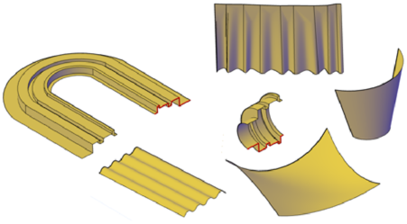
Use procedural surfaces to take advantage of associative modeling, and use NURBS surfaces to take advantage of sculpting with control vertices. The illustration below shows a procedural surface on the left, and a NURBS surface on the right.
3D Surface Modeling
A surface model is a thin shell that does not have mass or volume. AutoCAD provides two types of surfaces: procedural surfaces and NURBS surfaces.
- Use procedural surfaces to take advantage of associating surfaces with their defining curves.
- Use NURBS surfaces to take advantage of sculpting with control vertices.
One typical modeling workflow is to create basic models using meshes, solids, and procedural surfaces, and then convert them to NURBS surfaces for additional shaping.
You create surface models using many of the same tools that you use for solid models: sweeping, lofting, extruding, and revolving. You can also create surfaces by blending, patching, offsetting, filleting, and extending other surfaces.
Choose a Surface Creation Method
Create procedural and NURBS surfaces using the following methods:
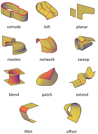
- Create surfaces from profiles. Create surfaces from profile shapes composed of lines and curves with EXTRUDE, LOFT, PLANESURF, REVOLVE, SURFNETWORK, and SWEEP.
- Create surfaces from other surfaces. Blend, patch, extend, fillet, and offset surfaces to create new surfaces (SURFBLEND, SURFPATCH, SURFEXTEND, SURFFILLET, and SURFOFFSET.
- Convert objects into procedural surfaces. Convert existing solids (including composite objects), surfaces, and meshes into procedural surfaces (CONVTOSURFACE).
- Convert procedural surfaces into NURBS surfaces. Some objects cannot be converted directly to NURBS (for example, mesh objects). In that case, convert the object to a procedural surface and then convert it to a NURBS surface (CONVTONURBS).
Understand Surface Continuity and Bulge Magnitude
Surface continuity and bulge magnitude are properties that are frequently used when creating surfaces. When you create a new surface, you can specify the continuity and bulge magnitude with special grips.
Continuity is a measure of how smoothly two curves or surfaces flow into each other. The type of continuity can be important if you need to export your surfaces to other applications.
Continuity types include the following:
- G0 (Position). Measures location only. If the edge of each surface is collinear, the positions of the surfaces are continuous (G0) at the edge curves. Note that two surfaces can meet at any angle and still have positional continuity.

- G1 (Tangency). Includes both positional and tangential continuity (G0 + G1). With tangentially continuous surfaces, the end tangents match at the common edges. The two surfaces appear to be traveling in the same direction at the join, but they may have very different apparent "speeds" (also called rates of change in direction, or curvature).

- G2 (Curvature). Includes positional, tangential, and curvature continuity (G0 + G1+G2). The two surfaces share the same curvature.

Bulge magnitude is a measure of how much surface curves or "bulges" as it flows into another surface. Magnitude can be between 0 and 1 where 0 is flat and 1 curves the most.
Set Surface Properties Before and After Creation
Set defaults that control a variety of surface properties before and after you create the surface objects.
- Surface modeling system variables. There are a number of system variables that are frequently used and changed during surface creation: SURFACEMODELINGMODE, SURFACEASSOCIATIVTIY, SURFACEASSOCIATIVITYDRAG, SURFACEAUTOTRIM, and SUBOBJSELECTIONMODE.
- Properties palette. Modifies properties for both the surface objects and their subobjects after they are created. For example, you can change the number of isolines in the U and V directions.
Source: https://knowledge.autodesk.com/support/autocad/learn-explore/caas/CloudHelp/cloudhelp/2018/ENU/AutoCAD-Core/files/GUID-8218FF9A-6F05-47E7-A39C-47D342B942EB-htm.html
0 Response to "Can You Draw a Surface in Autocad"
Post a Comment